


X-Ray High-Voltage Cable: Structure, Components & Performance Guide
In modern medical imaging, the X-ray machine serves as a cornerstone for diagnosis and treatment. While much attention is focused on the X-ray tube and generator, the high-voltage cable is the critical link that binds them together. Its structural integrity and performance directly determine the stability of the equipment and the clarity of the diagnostic images.
This article provides a detailed breakdown of the X-ray high-voltage cable structure and analyzes the key components that ensure safe and efficient operation.
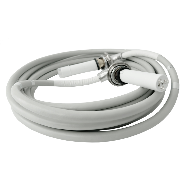
Detailed Analysis of the 7-Layer Structure
The high-voltage cable is responsible for transmitting high-voltage current from the generator to the X-ray tube to produce X-rays. Its construction is a precise engineering feat designed to handle extreme electrical stress while maintaining flexibility.
1. Outer Sheath: Typically made of Polyvinyl Chloride (PVC) or other materials resistant to high temperatures, oil, and corrosion. Its primary role is to provide mechanical protection for the internal components against abrasion and environmental factors.
2. Metallic Shielding Layer (Inner): Located beneath the sheath, this layer consists of braided metal wires or foil. It prevents external electromagnetic interference (EMI) from affecting the signal and contains the internal electric field.
3. Insulation Layer: Usually constructed from Polyethylene (PE) or Cross-Linked Polyethylene (XLPE), this layer surrounds the conductor. It is the most critical barrier, preventing high-voltage current leakage and ensuring electrical isolation.
4. Semiconductive Layer: Applied over the insulation to smooth out the electric field gradient and prevent partial discharges caused by tiny air gaps.
5. Core Conductors: The heart of the cable, typically made of multiple strands of fine copper wire twisted together. This design ensures excellent conductivity while maintaining the flexibility required for clinical use.
6. Fillers: Non-conductive materials used to fill the gaps between the core wires. This maintains the cable’s round shape, prevents the conductors from shifting, and enhances durability.
7. Ground Wire: Connects the metallic shielding layers to the earth ground. This is a vital safety feature that protects operators by diverting fault currents away from the equipment surface.
Key Component Breakdown
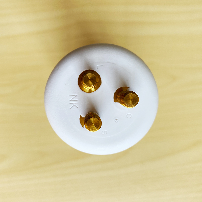
Beyond the layered diagram, the performance of the cable depends on the quality of specific elements:
• Conductors: The material (high-purity copper), diameter, and stranding technique directly impact the cable’s electrical conductivity and its mechanical tensile strength.
• Insulation Quality: The dielectric strength of the insulation material determines the cable’s maximum voltage rating and its service life. Any defect here risks catastrophic failure.
• Shielding Effectiveness: Robust shielding is essential for preventing electromagnetic noise that could degrade the X-ray image quality or interfere with nearby sensitive electronics.
• Grounding Integrity: A properly connected ground wire ensures that in the event of an insulation breach, the electrical current is safely dissipated, protecting both the patient and the operator.
Design Considerations
Designing an optimal high-voltage cable involves balancing multiple factors beyond basic technical specs. Engineers must consider the total cost of ownership, the weight of the cable (to ease handling fatigue), and the ease of installation and maintenance. The goal is to achieve the best possible performance and economic efficiency without compromising the safety standards required in a medical environment.